Craque-Mod Noise Toaster

Table of Contents
Why Synth DIY?#
My wife and I were talking recently about how we feel like we’re floating in a constantly numbing “Groundhog Day” fugue state. Instrument building is a super effective way to change my entire frame of mind, much like getting deep into an improvisation or track editing session. So while it’s not anywhere closely related to my day job, my unconscious probably doesn’t see it that way. Regardless, it serves to dissipate the stress all around me.
Synthesizer DIY (Do It Yourself) hardware builds have the advantage of being longer lasting than direct music making while still contributing to the creative process. There emerges a goal or problem to look forward to the next time I attend to the build, which aids in constructing discipline around it. This is something I have found critical during this period of jobless high stress, where I have no daily constructs to attach any discipline, to break me out of that gliding middle-consciousness state.
Make: Analog Synthesizers is a book penned by Ray Wilson of Music from Outer Space fame. Among other instructional features of the volume, it is also an expanded guide for constructing and understanding the Noise Toaster (NT) and all its sections and connections. I was quick to pick it up when it came out (May, 2013), I built a MFOS Voltage Quantizer for my Eurorack rig and wasn’t going to pass up his juicy Synth DIY book. So looking for some good short-term projects to accomplish stress reduction during my job search, I picked up the kit (the PCB with panel and all components, essentially everything but the case).
Knowing I could be unemployed for quite a while, the NT seemed like a perfect longer-term project. A real book in-hand that covered deep details and schematics meant it was ripe for modification. What were the decisions I faced along the way? How did I approach them? What was the result?
Keep reading for a breakdown of the major features and how my experience in DIY guided my choices to completion. Or just check out the pictures, they are pretty neat. If you can’t wait to hear it, skip to the end for links.
Core Noise#
Accommodating case#
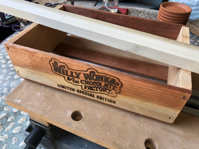
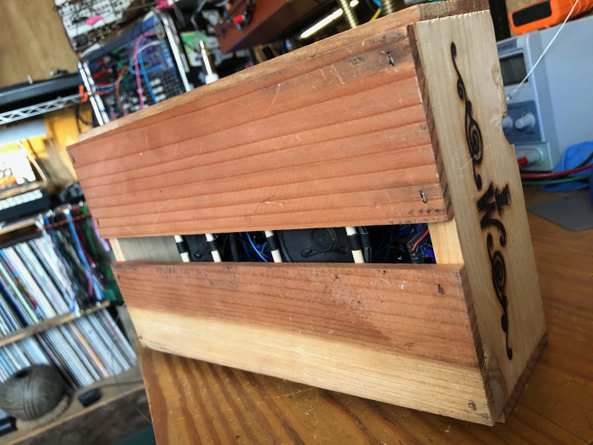
I keep a lot of containers around for art projects, one of which was this “mini-crate” thing that was originally a vehicle for selling bunches of grapes at the supermarket. We got two of them (the grapes were good afterall) and saved them for projects because the sides have this cool wood-burnt “Willy Wonka and the Chocolate Factory ‘Limited Special Edition’” logo and a neat magical top-hat imprint on each end. Yes, this was a marketing gimmick from a horrible re-make of the original Dahl classic.
The 6.5" square panel of the NT fit nicely inside, there would be room for the components underneath, but mounting it would be an issue without rails. Close by were some 1x2 birch boards left over from a previous instrument prototype that I could use, they were exactly thick enough to provide an internal lip for panels instead of rails and could be cut to fit snugly within the mini-crate longways, supporting the panel above.
As I worked I decided not to use any metal hardware in the structure of the case itself. This is learned from experience: it’s incredibly difficult to work with very thin boards and things like screws, and this was basically a one-of-a-kind case in the first place, so actions that avoid physically altering the case itself were to be avoided. The internal wood walls and poles would be kept in place with friction, force, and a little gaffer’s tape.
Non-permanent fixtures#
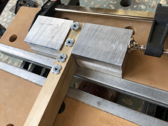
The front-plates and panels of synths and such things on wooden cases are typically attached with screws, scorned for this project. Interchangability has become an important aspect of my building, so naturally I prefer to support modularity in the design. I knew I’d want to remove and work on the internals from multiple angles and really wanted it to behave like multiple modules bolted onto a metal rail. This solution search met several dead-ends until I happened on these “T-nuts” (apparently for affixing things to climbing walls) that matched the nice black 4M hex-socket carbon steel bolts I had.
Thanks to an array of clamps and blocks of aluminum, I was able to coax these alien looking nuts into gripping the birch 1x2s, without splitting, close enough to the edge. This allowed internal clearance for the PCB and components, which I had to mount and wire up before making this decision so I could know what the space needed would be. I learned the hard way that drilling these by hand (another forced limitation) meant I needed to calibrate the next hole by placing the panel and tracing the hole onto the wood. So panel hardware was also a requirement at this point.
Modular panel design#
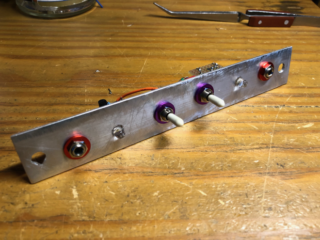
At my immediate disposal were long strips of thin aluminum, again left over from other projects. These fit nearly perfectly to fill the spaces left by the NT panel on the mini-crate case. Three of these panels would fit above the NT, and a thinner one below to hold the batteries. Where to mount the different panels in relation to the NT was a decision that involved thinking about how the internal wiring connections would be routed. The arrangement of controls also mattered, it was important that like-controls were grouped and coded for intuitive use. This prescribed which panels went in which location.
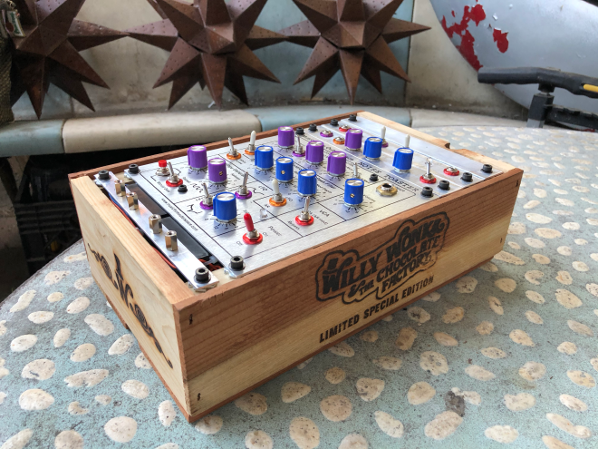
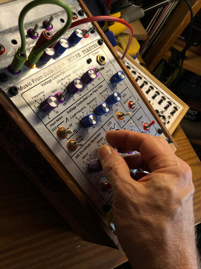
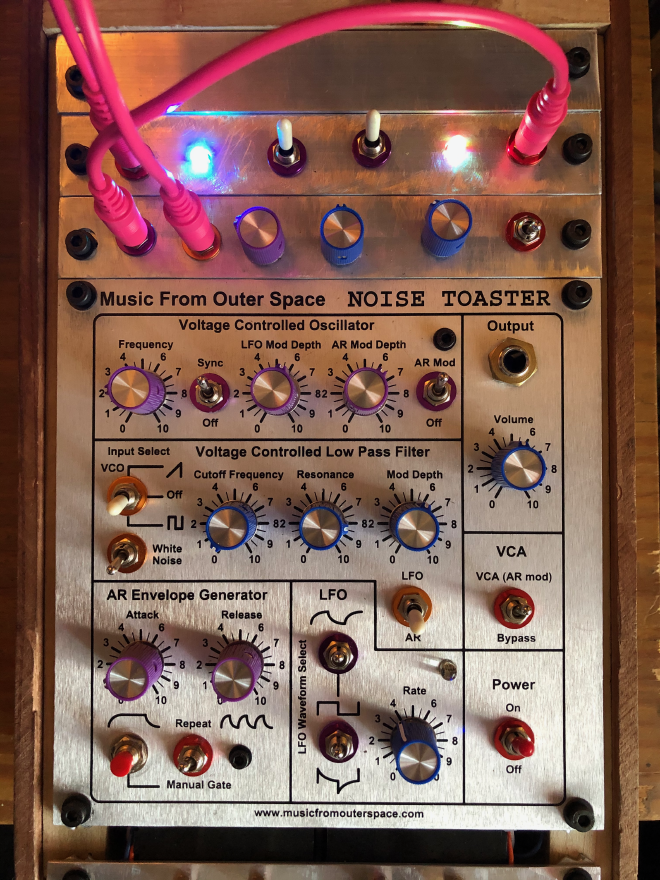
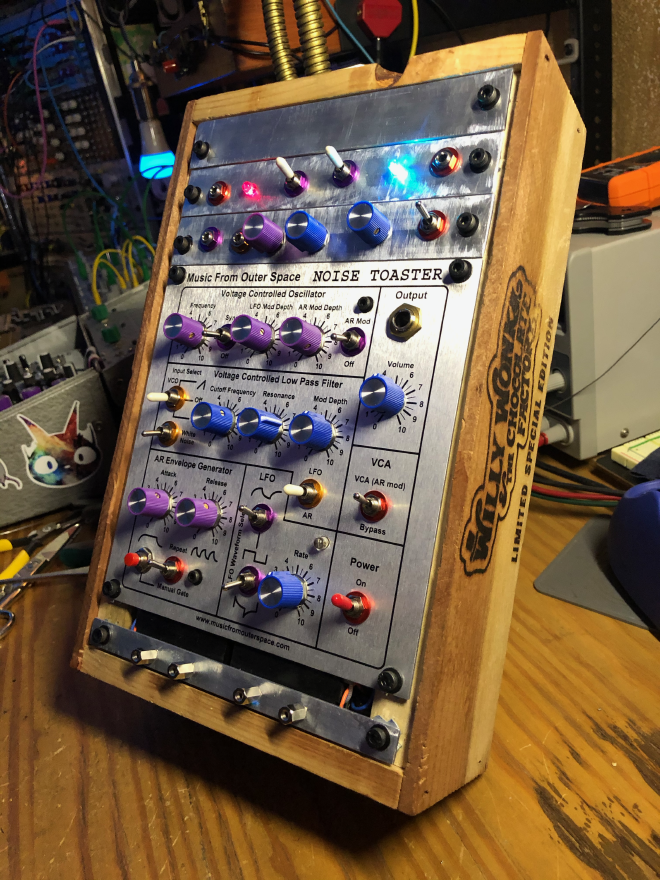
Color coded UX components#
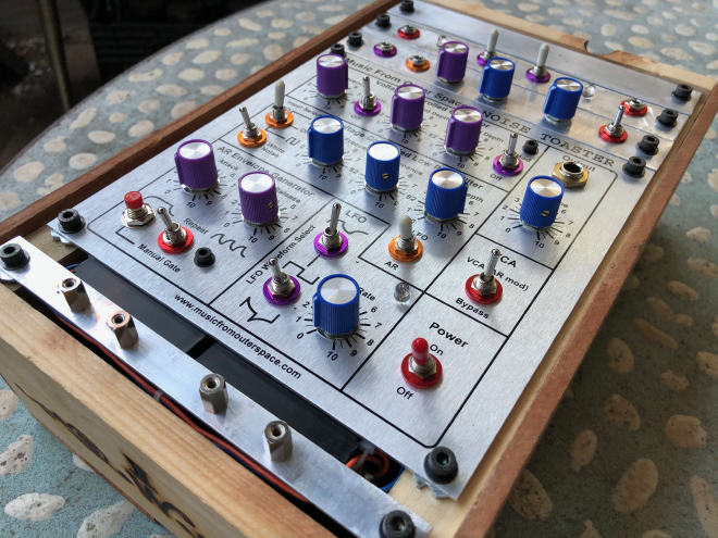
It’s difficult to break down how I made the decisions to use the panel components I did. In a couple of cases the hardware was simply what I had on hand. Someone made a comment that it was Buchla style colors but I didn’t intend that, I only knew I wanted a low-count functional color scheme. The main panel was produced by MFOS and looks great but mine are intentionally blank, instead relying on color coding: red washers indicate power and output controls, purple washers are for Voltage Controlled Oscillator (VCO) related things, gold for the Voltage Controlled Filter (VCF). The knobs also match function: purple for the VCO input, blue for the VCF input and Low Frequency Oscillator (LFO) Shaper. The external LFO features are gathered together on the right side of the device to roughly correspond to the LFO source controls, and the VCO features to the left. Multi-position switches (on-off-on) get white caps. All of this was obtained from the nice folks at Love my Switches (the same place I extoll in Knobbybrute).
Keep it battery powered#
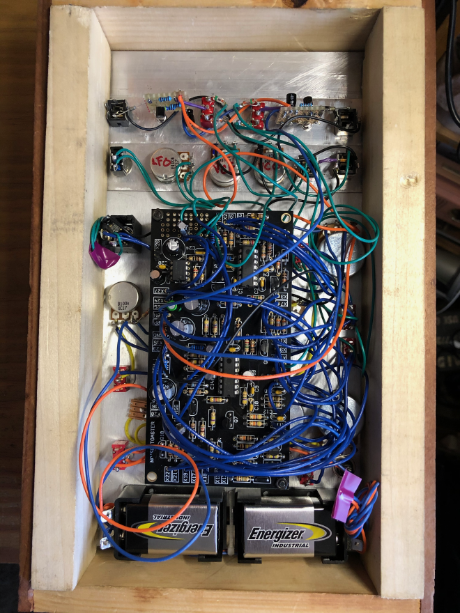
Like many of the MFOS projects, a 9 volt battery is all that’s needed. The unit doesn’t pull that much power with the line output (15mA, ~33 hours with one 9v) but with speakers attached that consumption climbs depending on the volume setting. Ray warns in the build guide that adding a capacitor at the provided holes in the PCB will provide a nice gain boost that eats up power quickly. Not to mention I wanted to add stuff. My solution? Jeremy Clarkson said it best: MORE POWER! Indeed, a panel could fit two 9v battery holders end-to-end. Wire these bad boys in parallel to provide nearly an amp-hour of power and that is plenty of overhead for additional circuitry and expansion modules, plus ample room for a boost switch. This battery pack becomes a module itself, pulling out from the front for easy reloading.
Mod Squad#
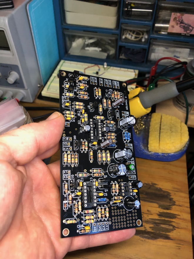
In many cases, I took advantage of the grid of pads/holes included in the corner of the PCB. For instance, pulling the LFO Shaper resistor out to that area makes it easy for repairs. It also made adding the Boost Switch a lot easier.
Boost Switch#
This is a speaker output gain stage, it will not affect the line output. Yes, Ray speaks of this in the documentation with big bold letters that adding a 10µF capacitor to the speaker OpAmp circuit will suck battery power fast, delivering a greater electrical punch to the amplifier. To do this mod and not cause undue battery depletion, I put it behind a switch. When the switch is ON, the path to the capacitor completes and full power to the speaker engine is accomplished.
Parallel Speakers#
The key here is impedance matching. Ray prescribes up to 32Ω, so I had room to combine the kit’s nicely wired 2" 1W/16Ω speaker with a spare 1" 1W/8Ω speaker I had in the parts bin. Speakers in parallel have an overall impedance value that is lower than the sum, so even without considering that I was well under the rating for the output of the NT. Mounting them would have to be a creative discovery, it becomes one of the final steps in construction: wooden rods criss-cross to hold them above the floor of the case, doubling as structural elements for keeping the other wood walls in place.
Ray’s VCO and VCF inputs#
These are CV and Audio mods respectively, there was no question about adding them. Holes also exist on the PCB precisely for this purpose, and are explained in detail in the NT docs. The VCO input is described as simply a “modulation source”, specifically it is exponential modulation that tracks with things like sequencers and what you would normally use with 1v/octave inputs on a regular synth. Keeping in mind this VCO is not meant to be accurate or at all close to tracking anything. The VCF input is an audio input, and since it’s possible to turn off the main VCO-to-VCF connection, other audio sources can use it. So can my custom output/effector module.
LFO Shaper#
There is a notice on the MFOS web docs for the NT that explains using a 20kΩ resistor in place of a 75kΩ one in the design affects how “deeply” the LFO can modulate the filter while the LFO is in integrated (basically combined ramp/square) mode. The kit I bought contains both resistors as described, with the option to use either one as desired. That’s when “variable resistor” alarms go off in my brain, and voila the birth of LFO shape control knob. This is the final piece of the first expansion module seen at the top of the NT.
VCO and LFO outputs#
While I was planning wiring and soldering the PCB I was extremely careful to note and map the nodes of things I wanted to break out. There are a healthy handful, some with more and less effect on the circuit should they be bent into service. Among these are the white noise (which I have many many other places) and Attack/Release Envelope Generator (AREG… which I didn’t want to touch), plus all the oscillators. This is the mod where I had the least knowledge of what would happen when certain things are connected, or what would end up being actually useful. This evolved into a circuit bending rabbit hole. Nevertheless, I went with a quartet of: VCO Square or VCO Ramp through one switch, LFO Square or LFO Integrated through the other, both with OFF positions as well. This is also where I began to think about LEDs, and what blinkenlites I could add to the build.
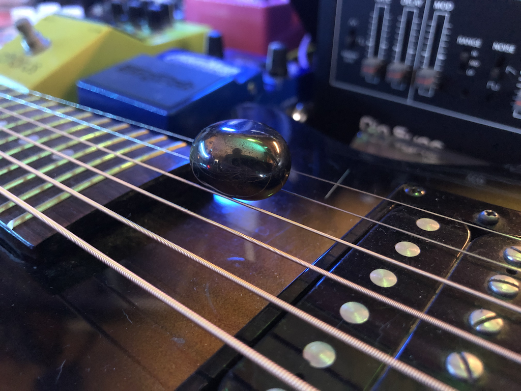
Multi-color LED output/effector#
Originally I simply wanted to replace the boring red LED that comes in the kit and have some kind of light display somewhere else that matched with some kind of signal being produced. As with many of these mods, I performed some basic research on the behaviors of devices I was modifying and adding to the circuitry, but not so much on how they may affect the sound. This is in some way the entire point: I openly welcome these kinds of blind discoveries spurred by what might be taken as “error” in a more refined, sacred model. This is one reason why I find this activity enthralling and able to break fixation. Adding the LEDs as I did was a massive reframe of my original intentions, and improvising the design around the balance of the circuitry first with the outcome of the sound second helped me exploit the more solid knowledge I have of DIY electronics to experiment with the way a certain arrangement of known electrical relationships would end up sounding.
LEDs are diodes (allowing electrons to move in only one direction) of a special kind that emit photons when a particular electron movement is required across a band gap of the semiconductor when power is applied, translating to specific wavelengths of light. Only the electrons in a red LED that are excited along red wavelengths (~650nm) are emitted by the diode, extremely efficiently and reliably so. I happened to have a handful of three-pin multi-color LEDs I found in a surplus store, so I looked into how they are used with a driver like a transistor or 555 timer. Forest Mims’s Optoelectronic Circuits was consulted, plus Ray has a blurb about LED drivers in the Make book as well. I needed this to be simple and installable behind a small panel, so a NPN transistor solution was apt for color control of the LED.
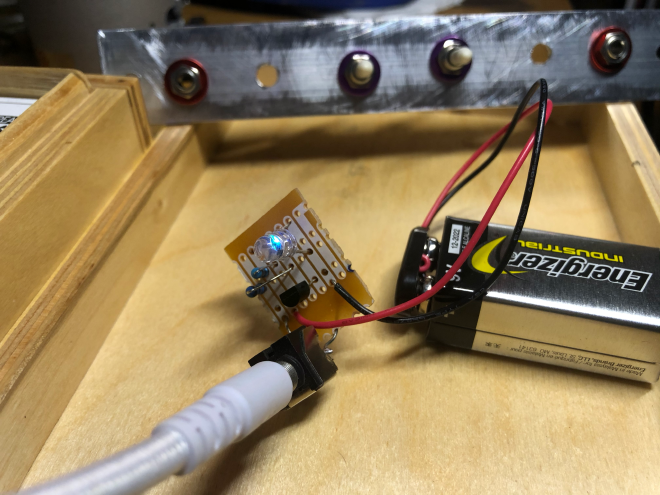
Here I built a test fixture, because I needed to see how practical my transistor driver design was. The plan was that each output would trigger the transistor to light the LED at a rate that matched the voltage envelope of the audio. This is known as Pulse Wave Modulation (PWM) via primitive Analog-to-Digital (A/D) conversion. The 47kΩ resistor used here with a 2N3904 NPN transistor passes voltages around 1v or higher that turn the transistor - ergo the LED - on. When I had it working I also now knew enough to make a shim that would effectively allow me to replace the main red LED with the multi-color one. No transistor is needed here because of the position of this LED in the LFO circuit, it would get PWM for free. At high rates, it would look red just like the one included in the kit. At low rates, all kinds of wonderful cyan-green-blue combinations.
Now comes the surprise. LEDs are often exploited for their diode-ness first and their light-ness second. For example I have a limiter/compression module that uses LEDs as an active part of the circuit. There are “ladder filters” out there that use them this way, a recent chaos module I built uses an internal LED as a source of uncertainty. I shouldn’t have been that surprised when I got the NT to operational mode and began experimenting that the LEDs and their drivers connected with the outputs I had chosen were affecting the nature of the sound. I didn’t mind at all. This is what circuit bending is all about!
What I had planned was a simple way to break out the internal signals of the NT. What I got was a beast of a different shade: an output module that could not only be patched to the inputs, not only be patched efficiently to external things, but could also significantly change the sound of the NT in a performable way without being patched at all.
When the VCO / LFO “output” switches are engaged, the nature of the one-way circuitry in the module causes what is effectively backpressure on the primary NT circuit, immediately changing its entire profile. This took some intense balancing and buffering experimentation to make it controllable. I tried 5-6 different types of additional diodes (zener on the main outputs in front of a 1kΩ impedance-raising resistor and germanium on the path from each signal on the NT) and several arrangements of pull-down resistors (which never made it to the final design). Diode placement and capacitor additions stabilized things just enough that I could control how different sources and positions did or did not affect the device with much greater accuracy and less susceptibility to noise and clicking across the mixed ground and reference voltages.
It’s true that a circuit like this could probably have been fully designed and improved with all kinds of clamping and filters with less guessing about component values. When this clearly became a circuit bending project instead of the designed/provided/tested input modifications, any fixations about strict design went out the window. Make the circuit electrically robust at the very least, then dive in with chaos until the result is sufficiently awesome.
Check It Out#
If you read this far, I hope your creativity nerves have been tingling and you’re ready to get started on that brain-reframing next masterpiece!
The thing about the mind is that although we’re certainly reframing when we move from one context to another, for me it does something more. I feel that it actually helps build unconscious relationships about the things I’m letting soak or ignoring completely. It is exercising my intuition and decision making skills, as I’ve illustrated in the examples above. Nevertheless, the very things from which I needed total escape have found their way into the spirit of this instrument as a part of its richness and character.
Having Synth DIY as a respite recharges me for the personal extensibility I need to be there for those around me. In fact, it is an embodiment of the complex adaptation my wife and I have faced over the three month gestation period of the Craque-Mod Noise Toaster. Music is healing, in its many forms.
Links#
The Wednesday 10/21 variability in response session features the instrument in full integration with the modular. You can hear its first growling filtered sawtooth right near the beginning and it appears throughout. Output is through a modified DOD FX90 delay pedal before routing into the modular for mixing. The output/effector LFO side is enabled, sending the square wave output to trigger a slew limiter (MN Maths) that is in turn modifying the cutoff for a Moog Werkstatt that is heard as a slow-rolling, droning bass. A four-step sequencer (MN Pressure Points) is the input for the VCO. You can see the NT waaaay in the back underneath the bookshelves.
This short IGTV video shows some of the differences in (one installed at the time) speaker with and without boost and then plugging the device through the delay pedal and a small amp to play a five minute etude. This also shows some self-patching!