My synth project: complete!
Here’s something I thought I’d never see myself do in my own lifetime: build a synthesizer from scratch.
Actually it’s a simple design: 2 555 timers in astable configuration producing square-waves. This means it’s a burst of sound every interval, pretty annoying and not very useful except for maybe starting earthquakes. So to give it a little flavor, I put a low-pass, 2-pole filter on the output of each oscillator, using a traditional operational amplifier.

A bit over a year ago it started out as a learning experience for me, I had never gotten into building things with analog circuitry – although I dated a chick in college who was an EE, so I was vaguely familiar with a breadboard. As a result, my design is über simple, and in reality was the design I could “get to work” from the opamp (a weird beast in itself, I will be tackling it again soon enough).
After a lot of experimentation and research on the web (these days a DIY’ers first reference), I came up with a 2-rail power design that provided 9V for the oscillators and 4.5V for the bipolar opamp (just left of the battery in the schematic). Moving left, the 741 opamp (NTE941) provides a low-pass, 2-pole filter to the signal from the 555 timer (NTE955).

The cutoff frequency of the filter is controlled with a potentiometer, as is the pitch of the oscillator. You can also see my modification in the lower left for a “range” switch, which wasn’t on the breadboard prototype, but made it onto my final PCB because I think it adds a lot more interest and possibilities.
This was an intense project, no doubt. I got some training on soldering little kits that got made into sculpture, and I am a proud builder and owner of a bleep labs thingamakit, and have recently built the wave sheild for my new arduino board (which I haven’t quite gotten to work yet, so I hope it’s my programming skills and not my soldering skills).
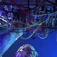
As much as I tried to plan out wire distribution inside the chassis where the pots and switches would not interfere too much with the PCB, sure enough I drilled the holes sort of on the wrong end of the enclosure, so the edges don’t match unless I flipped it, and of course I only discover this after everything is screwed into the front. So, fixing it meant pulling all the knobs and switches back out, and removing the PCB from its mount on the inside and flipping it 180 degrees, then re-attaching everything.
In the end it really didn’t make that much of a difference and the whole thing came together fairly perfectly anyway. What I haven’t really done is add any decoration or labels, which I do want to do… inspiration will strike when I least expect it, perhaps it will not only get illustration but also a name, and it will evolve!